Full beam wood design can be performed on Wood Joist Products based on the NDS and CSA wood engineering codes. The allowable moment and shear values were obtained from manufacturer's catalogs. Each database of I-Joists are specified by an XML file in the I-Joist sub-directory of the RISA Wood Schedules directory. The location of this directory is based on the information in the File Locations tab of the Tools - Application Settings dialog. The default XML files are listed below:
The various Wood Product databases may be accessed from the Beams
spreadsheet by clicking in the Shape field and then clicking
![]() .
.
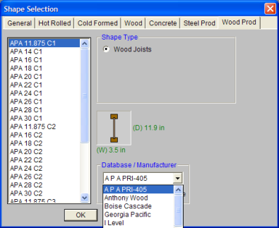
The Wood Product database is based on data contained in the product’s manufacturer's catalog. You may choose the Manufacturer and product from the drop down lists.
When you return to the Beams spreadsheet you will notice that a special label has been used to represent the choices that you made in the database. You may also type in this designation directly.
For additional advice on this topic, please see the RISA Tips & Tricks webpage at risa.com/post/support. Type in Search keywords: I-joists.
The APA Performance rated I-Joists bring standardization to the wood I-Joist industry. The standard provides design information for numerous types and sizes of I-Joists. This document is a draft version and is scheduled to be published soon. For all the design values that were used for this standard, refer the XML file located in the “I-Joist" sub-directory of the RISA Wood Schedules directory. For more information refer to APA website: www.apawood.org
Each database of I-Joists are specified by an XML file in the I-Joist sub-directory of the RISA Wood Schedules directory. The location of this directory is based on the information in the File Locations tab of the Tools - Application Settings dialog.
The program comes pre-loaded with XML files each of which contain a database of the manufacturers I-Joists:
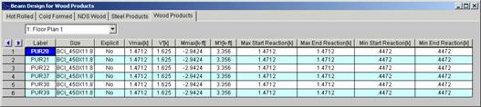
The name of the XML file itself will be used in the list of databases in the Wood Products Dialog. The first sheet of the XML file contains all of the joist name, joist size for rendering purposes, and design information used for each I-Joist. All fields are required information and if they are not provided or are left blank, then that I-Joist will not be available for use in that database. The Label field is used to identify the I-Joist and this field must be a unique name. The Depth, Flange Width, Thickness, and Web Thick entries are used to render the I-Joist shapes. The Joist Wt is used to calculate the self weight of the I-Joist. The maximum moment and shear forces are used as the allowables and are described below as V' and M'. The EI and the K, shear deformation coefficient is used in the deflection equation:
The NDS code applies adjustment factors to the allowable moments and shears of a wood joist. Currently RISAFloor only accounts for the Load Duration Factor CD. The other adjustment factors (CL, Cm, Cr, Ct, and CH) are all applied as 1.0.
The CD factor is entered on the Load Combination spreadsheet for each load combination that you want to use for wood code checks. If this field is left blank, it will be automatically calculated by the program. Different load combinations will have different CD factors. The CD factor will only be applied to wood code checks on wood members. See the Table below for the CD factors that are assumed for the various load categories. Note that the CD factor used for a load combination will be for the load category with the shortest load duration in that load combination.
| Load Category | CD |
|---|---|
|
DLPre |
0.9 |
|
LLConst |
1.25 |
|
DLConst |
1.25 |
|
DL |
0.9 |
|
LL |
1.0 |
|
LLS |
1.0 |
|
RLL |
1.0 |
|
SL |
1.15 |
|
SLN |
1.15 |
|
RL |
1.15 |
|
OL1, OL2, OL3, OL4 |
1.0 |
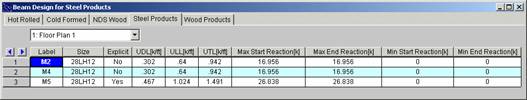
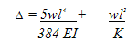
The results for the Steel and Wood Products tab are explained below. The steel product results give the uniform loads applied to the joists. The results for the wood products give the maximum bending moments and shears as well as the allowable moments and shears for the joist. The pull down list at the top of the spreadsheet allows you to toggle between floors.
The Label column lists the beam label.
The Size column displays the designation of the steel or wood product. When no adequate member could be found from the redesign list, this field will display the text “not designed”. Consider reframing, relaxing the design or deflection requirements (see Design Optimization), or adding more shapes to the available Redesign List (see Appendix A – Redesign Lists).
The Explicit column displays “Yes” if the beam has been locked to an explicit beam size by the user. When you have chosen a specific shape to override the programs automatic redesign, that beam becomes “locked” and will not be automatically redesigned by the program.
Note
The V max column for Wood Products displays the maximum applied shear that resulted from the load combinations that were selected for Wood Product design.
The V` column for Wood Products displays the allowable shear for the wood product under consideration. The program obtains this value from the manufacturers catalog.
The M max column for Wood Products displays the maximum applied moment that resulted from the load combinations that were selected for Wood Product design.
The M` column for Wood Products displays the allowable moment for the wood product under consideration. The program obtains this value from the manufacturers catalog.
Note:
The Max Start & End Reactions column displays the maximum start and end reactions of the beam for ALL load combinations. If “Show Factored End Reactions” in Model Settings is left unchecked, these displayed loads are not factored. If it is checked, then the displayed loads will have been multiplied by the factors in the load combinations. The sign convention assigns positive reactions to downward forces. Negative reactions, if they occur, would indicate uplift.
The Min Start & End Reactions column displays the minimum start and end reaction of the beam.
Shear deflection is only calculated for wood products that are pinned at both ends and have a uniform distributed load. Shear deflection may have significant effects for wood products, especially on beams with shorter spans.
RISAFloor does not check the maximum end reactions per the manufacturer's documentation. The end reactions and intermediate reactions including the bearing lengths must be checked outside of the RISAFloor program.
The Code Checks Spreadsheet summarizes the code check results for the beams and may be accessed by selecting Code Checks on the Results menu. The spreadsheet has five tabs: Hot Rolled, Cold Formed, Wood, Concrete, and Wood Products. The pull down list at the top of the spreadsheet allows you to toggle between floors.
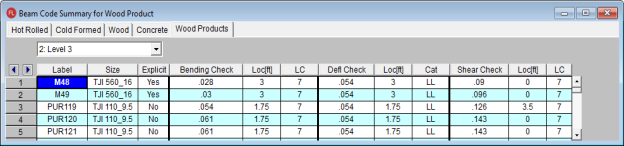
The Label column displays the beam label.
The Size column displays the beam size. When no adequate member could be found from the available shapes, this field will display the text "not designed". Consider re-framing, relaxing the design or deflection requirements (see Design Optimization), or adding more shapes to the available Redesign List (see Appendix A – Redesign Lists).
The Explicit column displays "Yes" if the beam has been locked to an explicit beam size by the user. When you have chosen a specific shape to override the programs automatic redesign, that beam becomes "locked" and will not be automatically redesigned by the program.
Note
The Bending Check and Shear Check columns display the maximum bending check and shear check calculated by the program. This value is equal to the actual bending or shear demand (stress or force) divided by the actually beam resistance (allowable stress or ultimate capacity). You can see the details of these values in the Bending Results or Shear Results spreadsheet. This check is calculated at 100 stations along each beam for each load combination and the maximum check is reported.
The Deflection Check displays the maximum deflection check. This value is equal to the ratio of actual deflection to allowable deflection. You can see the details of these values in the Deflection Results spreadsheet. This check is calculated at 100 stations along each beam and the maximum check is reported. See Beam Results - Deflection for more information.
The Location columns display the location along the member where the maximum bending, shear, or deflection check occurs.
The LC column displays the controlling load combination which resulted in the maximum bending or shear check.
Deflection checks are based on Load Categories (Dead, Live or DL+LL), not Load Combinations. Therefore, the controlling load Category for deflections is reported in the Cat column.
Shear deflection is only calculated for wood products that are pinned at both ends and have a uniform distributed load. Shear deflection may have significant effects for wood products, especially on beams with shorter spans.